Document Type: Exhibit Number: 6.01kkkk
Effective: 07-19-19
Revised: 04-27-22
Legal References: NFPA 70E
29 C.F.R.
1910.332
I.G.S.H.S 150
ARC FLASH AND SHOCK HAZARD CONTROLS IMPLEMENTATION PROCEDURE
I. INTRODUCTION
This Arc Flash and Shock Hazard Controls Procedure outlines the steps to be implemented by the City of Boise to ensure adequate protection for city employees and contractors exposed to electrical shock and arc flash.
This procedure applies to city personnel that are responsible for the examination, adjustment, maintenance, or inspection of electrical installations while energized. This standard also applies to all contractors that are responsible for examination, adjustment, maintenance, or inspection of electrical installations at city owned facilities.
II. IMPLEMENTATION
The implementation process for this procedure may be performed in three phases (Facility Managers or designees should be responsible for complete implementation):
A. Phase 1 should include short term activities including the following:
1. Develop an implementation plan to perform an Electrical Hazard Assessment (EHA) at each city facility in accordance with Section IV. The plan should include all activities required in future phases identified in this section.
2. Until the EHA has been performed, each facility should implement a temporary program for identification and avoidance of electrical hazards in accordance with Section VIII.
3. All Qualified Persons and Unqualified Persons that may work on or near energized equipment should receive appropriate training.
4. Procure minimally required Personal Protective Equipment (PPE) for expected arc flash and shock hazard.
B. Phase 2 should include long term activities including the following:
1. Perform an EHA at each city facility for all equipment operating at 480VAC or higher in accordance with Section IV.
2. Upon completion of the EHA, each facility shall:
a. Make appropriate corrections, upgrades, repairs to electrical equipment identified by EHA as not in compliance with NFPA 70, or to be not properly maintained per NFPA 70B.
b. Label all switchboards, panelboards, industrial control panels, motor control centers, and other similar electrical equipment that is likely to require examination, adjustment, servicing, or maintenance while energized.
c. Update employee training based on new information from completed assessment.
d. Develop an implementation plan to mitigate electrical hazards identified as exposing electrical workers to an unacceptable risk.
e. Procure additional electrical PPE as necessary based on information from assessment.
C. Phase 3 should include long term activities including the following:
1. Perform an EHA at each city facility for all equipment above 50V AC and below 480V AC in accordance with Section IV. Phase 2 and Phase 3 may be performed concurrently depending on facility size and resources.
2. Upon completion of the EHA, each facility shall:
a. Make appropriate corrections, upgrades, repairs to electrical equipment identified by EHA as not in compliance with NFPA 70, or to be not properly maintained per NFPA 70B.
b. Label all switchboards, panelboards, industrial control panels, motor control centers, and other similar electrical equipment that is likely to require examination, adjustment, servicing, or maintenance while energized.
c. Update employee training based on new information from completed assessment.
d. Develop an implementation plan to mitigate electrical hazards identified as exposing electrical workers to an unacceptable risk.
e. Procure additional electrical PPE as necessary based on information from assessment.
III. ELECTRICAL HAZARD ASSESSMENT PREPARATION
Necessary data for each facility EHA should be collected by a qualified person and results of the data collection should be included as a deliverable in accordance with Section XIV. Data required to complete the EHA includes:
• One-line diagrams
• Utility fault current data
• Equipment type (switchgear, switchboard, panelboard, MCC, etc.), manufacturer, model, voltage, amp rating, withstand rating
• Cable type, size, and length
• Protective device, type, manufacturer, model, trip settings and interrupt rating
• Transformer type and impedance
• Motor nameplate data (>50HP only)
• Industrial control panel data including nameplate Short Circuit Current Rating (SCCR)
IV. ELECTRICAL HAZARD ASSESSMENT
All city facilities should perform an EHA for their power system (see section XXI for Cost Considerations). The EHA is intended to identify the severity of electrical hazards, and to implement controls to limit the severity.
A. The EHA should include the following studies/analysis:
1. Short-Circuit Study: Calculate (through computer modeling and simulation) the 3-phase and 1-phase bolted fault current available at each bus in the electrical power system for all available sources. Utility fault current data and equipment data for all impedance devices are required for the analysis. If Utility data is not available, infinite primary may be used in conjunction with Utility transformer size and impedance.
2. Equipment Evaluation: Compare the calculated available bolted fault current to the current withstand rating for all equipment buses, and to the Available Interrupting Current (AIC) of protective devices. Equipment or devices that have a rating that is insufficient, it should be corrected before an arc flash label is applied to that equipment. If manufacturer approved series combination ratings are used to meet short-circuit capability requirements, the series rating should be documented on the equipment per NEC 2014 110.22(C). A completed Short-Circuit Study is a prerequisite to the Arc Flash Study.
3. Arc Flash Hazard Analysis (AFHA): Calculate (through computer modeling and simulation) the worst-case incident energy and arc flash boundary for all electrical equipment such as switchboards, panelboards, industrial control panels, meter socket enclosures, disconnect switches, bus duct and motor control centers that are likely to require to examination, adjustment, servicing, or maintenance while energized. Calculations should be performed using IEEE 1584-2002 calculation methods. Analysis results should indicate NFPA 70E 2021 recommended PPE based on incident energy level for use in equipment labeling.
4. Shock Hazard Analysis: Identification of equipment voltage for all equipment included in the AFHA, and the associated approach boundaries as defined in NFPA 70E 2021 Table 130.4(E)(a) for AC, and Table 130.4(D)(b) for DC.
5. Protective Device Coordination & Arc Flash Mitigation: A review of all protective device settings and clearing times to ensure that the device nearest to the fault clears first. In conjunction with the protective device coordination study, arc flash mitigation should be considered. All equipment with an “as found” incident energy in excess of 8 cal/cm^2 should be analyzed to determine if a circuit breaker settings adjustment or fuse class replacement would result in reduced incident energy. For new installations, engineering controls for coordination and arc flash mitigation should be considered, such as:
a. Current limiting fuses.
b. Arc resistant equipment.
c. Zone Selective Interlocking (ZSI).
d. Remote operation of devices.
e. Other new technologies designed to improve coordination and/or mitigate arc flash incident energy exposure.
B. The EHA should be updated when a major modification or renovation takes place. It should be review periodically, at intervals not to exceed 5 years to account for changes in the electrical system that could affect the results of the studies.
V. ELECTRICAL HAZARD ASSESSMENT DOCUMENTATION
Upon completion of the EHA for each facility, a documented report should be provided with the details of the analysis data, procedures, and results. At minimum the content of the document report should include:
A. Executive summary including the means and methods used to complete the analysis. The executive summary should identify:
1. Software used in analysis.
2. All assumptions made.
3. All deviations from IEEE 1584-2002 calculation method.
4. All deviations from procedures in NFPA 70E 2021.
5. Any NEC violations found or other corrective actions required.
6. Summary of each analysis performed.
B. Output reports from each of the analysis performed.
C. Time Current Curves (TCCs) from coordination and mitigation study.
D. Single-line diagram that all equipment included in the analysis.
E. Input data report.
VI. RISK ASSESSMENT
Risk assessment is a comprehensive review of hazards for specific tasks, and the means and methods required to minimize the risk. Risk assessment includes the following analysis:
A. Identification of the arc flash and shock hazards. This is done through the EHA.
B. Identifying specific tasks to be performed.
C. Documentation of the hazards associated with each task.
1. If documentation of the hazard associated with a specific task is not available, NFPA 70E 2021 Table 130.5(C) should be used to determine if arc flash is a hazard. Note that the “Equipment Condition” must be accounted for in the determination and if the requirements are not met than arc flash is always considered a hazard regardless of task for that equipment.
2. Exposure to live parts is always considered a shock hazard regardless of task.
D. Estimation of the risk associated with each hazard and task combination.
E. Determination of protective measures needed to reduce risk.
1. For arc flash hazards, the typical means to reduce the risk would include selecting and wearing the appropriate arc flash PPE based on equipment labeling.
2. For shock hazards, the typical means to reduce the risk would include voltage rated insulating PPE for all body parts that will cross the Restricted Approach Boundary with respect to live electrical parts.
3. Other protective measure that may be employed:
a. Remote switching/racking of devices
b. Insulated tools
c. Rubber insulated mats
d. Other new technologies that reduce arc flash and shock hazard risk
VII. EQUIPMENT LABELING
Upon completion of the EHA, electrical enclosures such as switchboards, panelboards, industrial control panels, meter socket enclosures, disconnect switches, bus duct and motor control centers that are likely to require to examination, adjustment, servicing, or maintenance while energized should be permanently labeled to warn qualified persons of potential arc flash and shock hazard.
Equipment labeling should meet the following requirements:
A. Labeling should meet ANSI Z535.4-2011 Standard.
B. Labels should be permanently affixed to equipment.
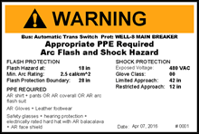
C. Labels for all equipment included as part of the AFHA should include the following:
1. Nominal system voltage.
2. Arc flash boundary.
3. Available incident energy at the working distance.
4. Recommended arc flash PPE based on NFPA 70E 2021 Table H.3.
5. Shock protection approach boundaries.
6. Date that analysis was performed.
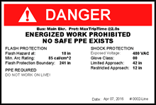
D. All equipment from the AFHA with a calorie rating above 40 cal/cm^2 should have a “Danger” in red label, while all labels 40 cal/cm^2 and below should have “Warning” in orange. The following are examples of labels for equipment included in the AFHA:
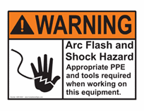
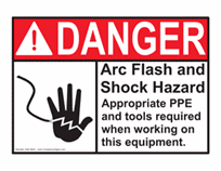
E. For all equipment not included in the AFHA, equipment should be labeled with generic warning or danger labels to comply with NEC 2014 110.16. The requirements of Section VII should be followed when determining the PPE to be used for equipment with generic labeling. The following are examples generic labeling:
VIII. TEMPORARY PROGRAM
Each facility should implement a plan to provide arc flash and shock hazard protection to workers before the EHA is completed and program implemented. The temporary program should include the following:
A. Arc flash hazard identification:
1. All electrical equipment such as switchboards, panelboards, industrial control panels, meter socket enclosures, disconnect switches, bus duct and motor control centers that are likely to require to examination, adjustment, servicing, or maintenance while energized, should be analyzed by a qualified person to identify a potential arc flash hazard.
2. The analysis should include the following:
a. The qualified person should identify the equipment involved and the a actual task to be performed, then utilize NFPA 70E 2021 Table 130.5(C) to determine if arc flash PPE is required. Note that the “Equipment Condition” must be accounted for in the table. If the “Equipment Condition” requirements are not satisfied PPE is always required and should be selected using the method below.
b. If arc flash PPE is required, then an Arc Flash PPE Category and Arc-Flash Boundary should be selected from NFPA 70E 2021 Table 130.7 (C)(15)(a) and (b).
c. The qualified person should then use NFPA 70E Table 130.7(C)(15)(c) to identify the proper arc flash PPE to be worn while inside the arc-flash boundary.
d. Information obtained from the NFPA 70E tables should be documented as part of the Energize Electrical Work Permit process.
B. Shock hazard identification:
1. All electrical equipment to which a worker will be exposed to live electrical
parts 50V AC or 100V DC and above should be analyzed by a qualified person to identify the potential electrical shock hazard.
2. The analysis should include the following:
a. The qualified person should identify if the live electrical parts are insulated or guarded from contact.
b. If it is determined that the live electrical parts are not insulated or guarded from contact, the requirements for the approach boundaries in NFPA 70E 2021 Table 130.4(E)(a) for AC, and Table 130.4(E)(b) for DC should be used.
c. Voltage rated, insulating PPE must be worn on any body part that crosses the Restricted Approach Boundary as identified above.
d. Note that the Approach Boundaries are for shock protection only and do not correlate with arc-flash protection or boundaries. In situations where both arc flash and shock hazards are present, boundaries associate with each must be considered.
IX. AUDITING
Understanding and compliance for this Regulation should be performed and documented as part of the annual field audit by the employee’s supervisor.
X. RECORDS RETENTION
Records for the EHA and all documented Risk Assessments should be kept and maintained for a minimum of 5 years or longer until replaced by an updated version.
XI. COST CONSIDERATIONS
The costs associated with implementation of this program may vary significantly depending on the following:
• Age, type, and amount of electrical gear/equipment (i.e. busbars, panelboards, switchgear, motor control centers, transformers, etc.) installed at a location.
• Installation of Permanent Electrical Safety Devices (i.e. voltage indicators)
• Amount and type of Arc Rated PPE required for personnel
• Insulated tools and other test instruments
A recently completed Electrical Hazard Assessment cost approximately $1125.00. This Electrical Hazard Assessment included the review of a motor pump VFD, a busbar, a transformer, an electrical disconnect, and a breaker panel. Also included in this Electrical Hazard Assessment are One-Line Diagrams, Time Current Curve graphs, an Arc Flash Report, Arc Flash Labels/Decals, and a Protection Device Settings Report.
PPE and Arc Rated single piece garments can cost anywhere from $50 up to $1300 for a complete Arc Flash Protection Kit. Shock protection gloves are required to be inspected and have a certified electrical rubber insulating glove test completed every 6 months by a qualified and accredited vendor. These glove test and inspections can cost up to $12 per glove pair.
Insulated tools range in cost from $200 to $1500 depending on the type and amount of tools needed. Volt/ohm meters can cost $40 to $600.